Why Understanding Smart Door Lock Components Matters
For system integrators, hardware distributors, and project-based buyers, understanding smart door lock components goes far beyond curiosity. Internal architecture determines:
Security level
Long-term durability
Environmental suitability
Maintenance cost
System integration compatibility
Unlike traditional mechanical locks, a smart lock is an electromechanical system. Its performance depends not only on the lock body but also on its electronic control system, authentication modules, motor drive structure, and power management design.
Many project failures occur not because of software issues, but because internal components are mismatched with real-world use cases — for example:
Undersized motor torque in high-traffic buildings
Inadequate sealing in outdoor installations
Poor PCB protection in humid environments
Weak clutch design causing mechanical fatigue
If you’re specifying products for residential developments, commercial buildings, or perimeter security projects, understanding how components interact is essential before procurement.
For a broader system-level overview, refer to our Smart Door Lock System Architecture, which explains how hardware, firmware, and integration layers connect within a complete smart access system.
The Core Components of a Smart Door Lock
A modern smart lock can be divided into four structural layers:
Exterior module
Interior module
Mechanical lock body
Control board & electronics
Each plays a distinct role in the overall smart door lock mechanism.
Exterior Module (Outer Assembly)
The exterior module is the primary user interface and first line of physical defense. It typically includes:
Capacitive fingerprint sensor
Touch keypad (anti-peep logic supported)
RFID card reader
Camera module (for video-enabled models)
Microphone & speaker (two-way communication)
Tamper detection switch
Waterproof sealing gasket
Fingerprint Sensor
Modern keypads support anti-peep password entry, allowing users to input random digits before or after the correct code. This protects against shoulder-surfing attacks — a common vulnerability in high-traffic buildings.
Touch Keypad & Anti-Peep Logic
Most commercial-grade smart locks use semiconductor (capacitive) fingerprint sensors. Compared to optical sensors, capacitive modules provide:
Faster recognition (typically < 0.5 seconds)
Higher resistance to spoofing
Lower power consumption
Industry benchmark data for biometric systems typically shows:
FAR (False Acceptance Rate): < 0.001%
FRR (False Rejection Rate): < 1%
These values vary depending on algorithm quality and MCU processing capacity.
Environmental Protection
For outdoor applications, sealing design becomes critical. Smart lock components exposed to rain and dust must comply with IP standards such as IP65 or IP67.
IP67-rated locks, for example, are:
Dust tight
Protected against immersion up to 1 meter for 30 minutes
Improper sealing around fingerprint sensors or charging ports often becomes the weak point in outdoor installations.
Interior Module (Inner Assembly)
The interior module houses the power system and motor drive mechanism. While less visible, it is critical to the reliability of the entire smart door lock mechanism.
Key components include:
Battery compartment
DC motor
Gear reduction system
Clutch mechanism
Manual thumbturn override
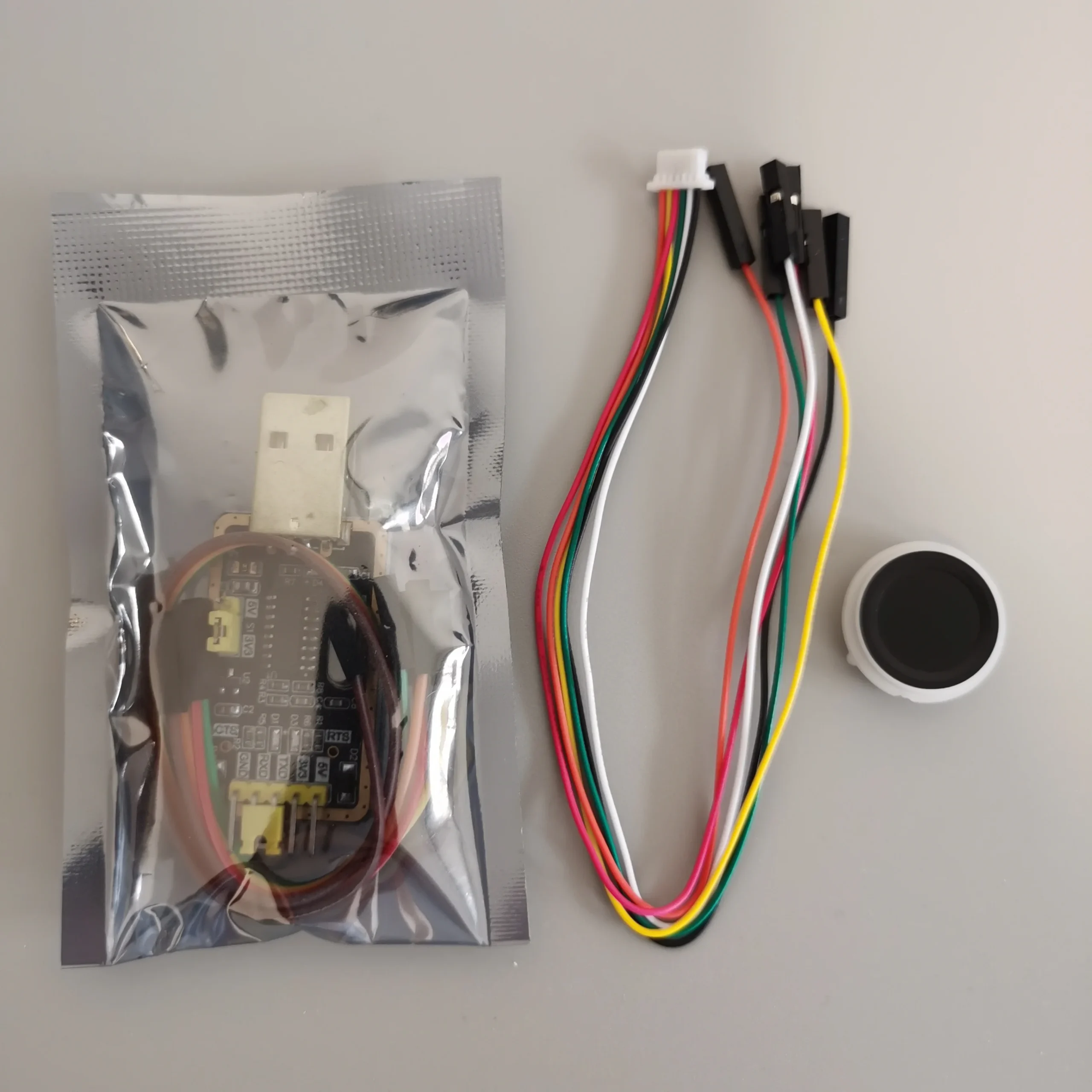
Reset & pairing button
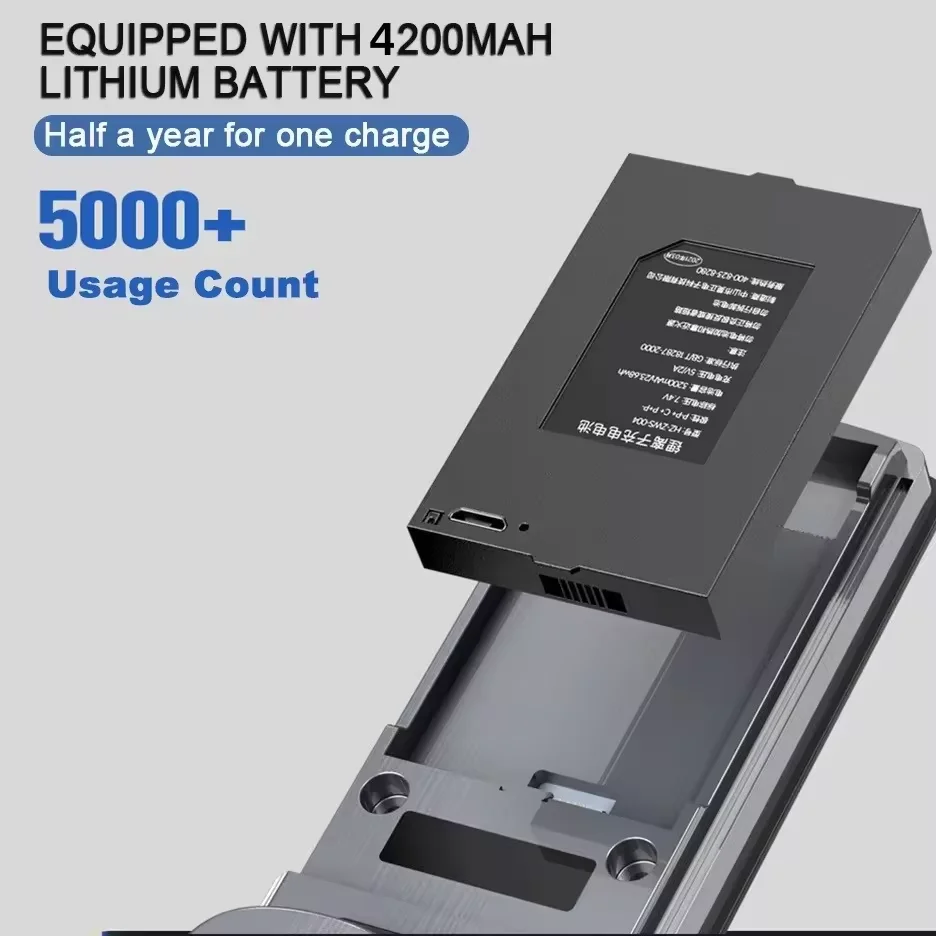
Battery System
Most residential smart locks operate on rechargeable lithium batteries ranging between 4000mAh and 10000mAh.
Typical electrical characteristics:
Standby current: < 100μA
Unlock peak current: 300–800mA
Battery life: 6–12 months (depending on usage frequency and wireless protocol)
Voltage monitoring circuits usually trigger low-battery warnings when voltage drops below approximately 4.8V–5.2V.
Many designs also include:
Type-C emergency power port
Reverse polarity protection
Overcharge protection circuit
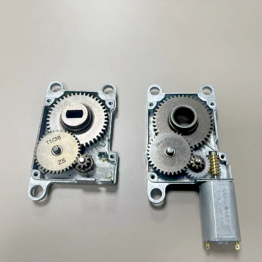
Motor Drive Unit
The motor is the mechanical actuator converting electrical signals into rotational force. Most smart locks use brushed DC motors with torque output typically between:
0.8–1.5 Nm (after gear reduction)
Higher torque may be required for:
Multipoint mortise systems
Heavy steel doors
High-frequency commercial usage
An undersized motor leads to increased wear and potential failure under load.
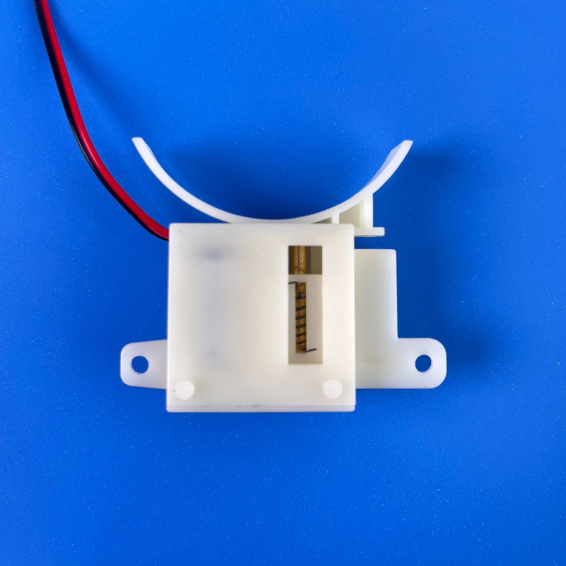
Clutch Mechanism
The clutch separates manual operation from motor-driven rotation. It protects internal gears by disengaging when excessive force is applied.
A well-designed clutch system:
Prevents gear stripping
Allows smooth manual override
Extends mechanical lifespan
Poor clutch engineering is one of the most common causes of internal smart lock component failure in low-quality products.
Mechanical Lock Body: The Structural Security Core
While exterior and interior modules manage authentication and power, the mechanical lock body remains the foundation of physical security. Regardless of how advanced the electronics are, the lock body ultimately determines resistance against forced entry.
There are three common lock body structures used in smart door lock components:
| Lock Type | Common Standard | Typical Backset | Security Grade | Typical Application |
|---|---|---|---|---|
Single Deadbolt |
ANSI/BHMA A156.36 |
60–70mm |
Grade 1–3 |
Residential doors |
European Mortise |
EN 12209 |
45–60mm |
Class 3–7 |
Apartment & wooden doors |
Multipoint Mortise |
EN 12209 / EN 14846 |
35–60mm |
High Security |
Steel & perimeter doors |
ANSI vs EN Standards
ANSI/BHMA Grade 1 locks are tested for up to 800,000 cycles and are typically specified for commercial environments.
EN 12209 defines mechanical durability and load resistance across European markets.
EN 14846 applies specifically to electromechanical locks.
For B2B buyers, the standard compliance of the lock body should match the project region and building code.
Deadbolt vs Mortise Structure
Deadbolt systems are simpler and easier to install but offer limited multi-directional locking.
Mortise systems allow:
Multiple latch points
Integrated anti-panic functions
Better compatibility with fire-rated doors
Multipoint structures significantly increase resistance against prying and door warping — particularly relevant in perimeter and outdoor installations.
Mechanical Durability Factors
Key structural elements affecting longevity:
Hardened steel latch bolt
Anti-saw bolt reinforcement
Solid brass cylinder (for mechanical override)
Reinforced strike plate
Mechanical security should never rely solely on electronic authentication. A robust smart door lock mechanism integrates both mechanical and electronic protection layers.
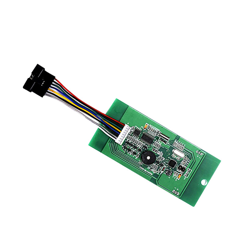
Control Board & Electronic Architecture (PCB System)
If the lock body is the physical core, the PCB is the intelligence center.
Smart lock components inside the control board typically include:
MCU (Microcontroller Unit)
Motor driver IC
Wireless communication module (BLE / WiFi / Zigbee)
Secure element chip
Power management IC
Memory storage module
Microcontroller Unit (MCU)
The MCU processes authentication data and executes lock/unlock logic.
Common characteristics in commercial smart locks:
Clock speed: 48–120 MHz
Flash memory: 256KB–1MB
RAM: 64KB–256KB
Higher processing capability allows:
Faster fingerprint matching
Encrypted communication handling
Multi-user data storage
Wireless Communication Modules
Depending on system architecture, locks may support:
Bluetooth 5.0 (10–30m indoor range)
WiFi 2.4GHz
Zigbee 3.0
Matter-over-Thread (in newer ecosystems)
Bluetooth is typically used for local control, while WiFi enables remote cloud access.
Power consumption differs significantly:
BLE standby consumption is lower
WiFi modules increase battery drain
This is why communication protocol choice directly impacts battery design.
Secure Element & Encryption
Modern smart lock components often integrate secure element chips to store:
Encryption keys
Authentication credentials
Device certificates
Industry-standard encryption typically includes:
AES-128 or AES-256
TLS communication protocols
This prevents replay attacks and data interception.
Smart Door Lock Working Mechanism Explained
Understanding the smart door lock mechanism requires examining the full workflow from user input to mechanical actuation.
Step 1: User Authentication
When a user interacts with the lock:
Input method activated (fingerprint / PIN / card / app)
Data captured by sensor module
Data encrypted inside MCU
Comparison with stored credential database
Authorization decision executed
Fingerprint recognition typically completes within 0.3–0.8 seconds depending on algorithm efficiency.
If authentication fails multiple times (commonly 5 consecutive attempts), the system triggers:
Temporary lockout
Audible alarm
Mobile notification (if connected)
Step 2: Motor Activation & Torque Transmission
Once authentication succeeds:
MCU sends signal to motor driver IC
DC motor activates
Gear reduction amplifies torque
Clutch engages with lock body spindle
Latch retracts
Motor torque (after reduction) typically ranges:
0.8–1.5 Nm
In multipoint systems, higher torque is required to drive additional locking points.
Gear quality plays a major role in lifespan. Metal gears significantly outperform plastic gears in high-frequency environments.
Step 3: Mechanical Engagement & Reset
After unlocking:
Spring system resets latch
Clutch disengages
Motor returns to standby mode
System re-enters low-power state (<100μA standby current)
If the battery is depleted:
Mechanical key override remains functional
Emergency Type-C power input can temporarily energize the PCB
This fail-secure design ensures access continuity without compromising security.
For a broader understanding of how mechanical, electronic, and communication layers integrate, refer to the Complete Smart Door Lock Technical Guide, which explains the full system architecture beyond individual components.
Security Technologies Embedded in Smart Lock Components
A secure smart door lock mechanism is never built around a single layer of protection. Instead, it combines biometric authentication, encrypted communication, mechanical resistance, and system-level defense logic.
Below is a breakdown of the security layers inside modern smart door lock components:
| Security Layer | Function | Risk Mitigated |
|---|---|---|
Biometric Authentication |
Verifies user identity |
Unauthorized access |
Encrypted Communication |
Protects data transmission |
Data interception |
Lockout Logic |
Disables system after failed attempts |
Brute-force attack |
Tamper Detection Switch |
Detects forced removal |
Physical manipulation |
Secure Element Chip |
Stores encryption keys securely |
Credential extraction |
Mechanical Override |
Maintains access during failure |
System downtime |
Anti-Peep & Anti-Brute-Force Logic
Most commercial-grade smart locks support:
Anti-peep password input
Lockout after 5 incorrect attempts
1–5 minute temporary system freeze
These functions prevent simple social engineering or repetitive guessing attacks.
Encryption Standards
Data exchanged between the lock and mobile devices or gateways is typically protected using:
AES-128 / AES-256 encryption
TLS-secured communication (for cloud systems)
AES-128 remains widely used due to its balance between security and processing efficiency for embedded systems.
Tamper Detection
Internal tamper switches trigger alerts when:
The exterior panel is removed
Abnormal vibration is detected
The PCB is exposed
In connected systems, alerts can be transmitted instantly to mobile applications or central management platforms.
Security should be evaluated not only by authentication method but by how all smart lock components interact under abnormal conditions.
Power Management & Battery Engineering
Power design is one of the most underestimated smart door lock components.
Electrical Consumption Profile
Typical operating profile:
Standby current: < 100μA
Bluetooth active: 5–15mA
WiFi active: 80–200mA
Motor activation peak: 300–800mA
Because motor activation is short-duration, standby consumption has greater long-term impact on battery life.
Battery Life Expectation
For residential usage (5–10 unlocks per day):
4000–5000mAh battery → ~6–8 months
8000–10000mAh battery → up to 12 months
Cold environments significantly reduce lithium battery efficiency. At -20°C, effective capacity may drop by 30–40%.
Therefore, climate conditions must be considered when specifying outdoor smart locks.
Low-Battery Safeguards
Modern smart lock mechanisms include:
Multi-stage low voltage warning
App notification alerts
Audible reminders
Emergency power port
Mechanical key override
A professionally engineered system always ensures access continuity even under power failure.
How Component Design Impacts Real-World Applications
The internal structure of smart door lock components directly determines project suitability.
Residential Installations
Focus on low standby current
Balanced motor torque
Quiet operation
Compact lock body
Multi-Family & Apartment Buildings
Higher cycle durability (ANSI Grade 1 recommended)
Stronger gear materials
Stable wireless communication
Commercial & High-Traffic Sites
Metal gear motor system
Reinforced clutch
Industrial-grade PCB coating
Higher torque capacity
Outdoor & Perimeter Gates
IP65–IP68 sealing
Anti-corrosion housing
Temperature-resistant battery system
Waterproof charging interface
Selecting a smart lock based solely on features (fingerprint, app, keypad) ignores the underlying structural architecture that determines long-term reliability.
For a comprehensive understanding of how these components integrate into complete residential and commercial access systems, refer to the Smart Door Lock Design & Selection for specification-level evaluation criteria.
Frequently Asked Questions
What are the main components of a smart door lock?
A smart lock consists of four structural layers: exterior module (authentication interface), interior module (motor and battery system), mechanical lock body (physical security core), and PCB control board (electronic logic). Each layer performs a distinct function within the overall smart door lock mechanism.
How does a smart door lock mechanism work internally?
After authentication (fingerprint, PIN, card, or app), the MCU verifies credentials, activates the motor driver, engages the clutch system, and retracts the latch through gear reduction. After unlocking, the system resets and returns to low-power standby mode.
What type of motor is used in smart locks?
Most smart locks use brushed DC motors combined with gear reduction systems. Torque output typically ranges between 0.8–1.5 Nm. Higher torque is required for multipoint mortise structures or heavy steel doors.
What happens if the battery dies completely?
Well-designed smart lock components include:
Mechanical key override
Emergency Type-C power port
Low-battery warnings before shutdown
Access continuity is maintained even if the battery is fully depleted.
Are smart lock components waterproof?
Not all models are designed for outdoor use. Outdoor-rated locks typically comply with IP65 or IP67 standards. Waterproofing depends on sealing structure, gasket quality, and protected charging ports.
How secure is the encryption inside smart locks?
Most modern systems use AES-128 or AES-256 encryption combined with secure element chips for key storage. Security depends on implementation quality, not encryption label alone.
Can individual smart lock components be replaced?
In professional-grade systems, PCB boards, motors, and lock bodies can sometimes be serviced separately. However, low-cost consumer locks often use integrated designs that require full unit replacement.
What is the difference between a smart lock PCB and a traditional electronic lock board?
A smart lock PCB integrates wireless communication, encrypted credential storage, biometric processing, and motor control in one board. Traditional electronic locks often lack encrypted communication and remote management capability.
Final Consideration
Understanding smart door lock components is not just a technical exercise — it is a prerequisite for correct specification, risk evaluation, and long-term reliability planning.
Project-level decisions should be based on:
Mechanical standard compliance
Motor and clutch engineering
Encryption implementation
Power management design
Environmental suitability
If you’re evaluating smart lock systems for residential, commercial, or perimeter applications, reviewing the complete structural architecture is essential before procurement.
Explore our Smart Door Locks to understand how internal components, system integration, and application scenarios connect within a full smart access ecosystem.
high-traffic commercial. Full OEM/ODM technical support.